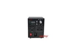
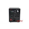


Machine Vision Light Intensity Control External Trigger Input Constant voltage system
Product Features
PBT-6024 series are outfit with wower cut memory, setting lock,fault detection , warning function.
Compared with normal control unit, this control unit can improve the light intensity 3 times higher.
Four circuits can be controlled seperately and the lighting time can be set from 10 to 990us.
The trigger output function can activate the camera synchronously.
DIN rail mounting availability.
External EIA-485 communication command input.
Model No. Demonstration:
|
PBT- |
60 |
24 |
- |
4 |
|
Series |
Power |
Output voltage |
|
No. of channels |
*Feature:24V/digital light intensity cotrol/compliance with RoHS directive/wide voltage 110-240V/Over current protection/Powerboot restore.
Specification:
| Model | PBT-6024-4 | PBT-10024-4 |
| Input Voltage | AC100-240V | |
| Inrush Current | 17A(AC100V),35A(AC240V*cool start) | 35A(AC115V),70A(AC230V)*cool start |
| Output | DC48V 5A MAX | DC48V 8A MAX |
| Outout Power | 4 channels in total:60W max | 4 channels in total:100W max |
| Lighting Time | 10-990µs | |
| Lighting Intensity Set | The light intensity is set as 10% to 100% of the pulse width | |
| Lighting Delay | 6µs MAX | |
| Trigger Function | YES | |
| Trigger Input Voltage | 5-24V | |
| Trigger Output Voltage | 5V | |
| Overload Protection | Activated when output current overload 7% or higher, reset by reopening the power supply. | |
| Weight | 1kg | 2kg |
| Standard Accessory | External trigger input cable, AC power cable | |
| Optional Accessory | EIA-485 communications cable(Length:3m), EIA-485 to RS232 adaptor, RS232 to USB serial cable. | |
| External control connection port | Trigger Input: MIL connector,10 pins | |
| Lighting intensity /Lighting mode setting: e-CON interface,3 pins | ||
Dimension Diagram

Accessories
1.External trigger input cable (Model TRI-3)--Optional Accessory.
External trigger signal connection example.
External trigger input explanation
| Trigger connection method | Trigger input | Trigger Output | |||||||||
| Port | 1 | 2 | 3 | 4 | 10 | 5 | 6 | 7 | 8 | 9 | |
| Channel | L1 | L2 | L3 | L4 | common+ | L1 | L2 | L3 | L4 | common- | |
| Wire color | brown | orange | yellow | black | red | blue | green | purple | gray | white | |
External trigger input cable dimension(mm)
2 EIA-485 communications cable(Mode:485C-3) -Optional Accessory
PC communication connect method ,Communication connect description
EIA-485 communication cable dimension.(mm)
3.EIA-485 to RS232 adaptor (Model: UT-201B) -Standard accessory
Specification of serial port communication
1, Comunication Specification
| Communication protocol | Work manner | Baud rate | Transport format | |||
| RS485 | Half duplex | 19200bps | Start bit | Data bit length | Parity bite | Stop bit |
| 1 | 8 | 0 | 1 | |||
"Checksum calculation method: Accumulate all bytes from <Header> to <ID> by hexadecimal and selec the latest two bytes of the result, then transfer it into 2 bytes ASCII code. Eg: The hexadecimal accumulate result is 1E2. selec "E2". The 2 bytes ASCII code is 045, 032."
2, Channel Specification
| Channel | L1 | L2 | L3 | L4 | L5 | L6 | L7 | L8 |
| Value | 00 | 01 | 02 | 03 | 04 | 05 | 06 | 07 |
3 Lighting Mode
| Light Mode | F00 | F01 | F02 | F03 | F04 | F05 | F06 | F07 | F08 | F09 | F10 |
| Value | 00 | 01 | 02 | 03 | 04 | 05 | 06 | 07 | 08 | 09 | 10 |
| Mode | Constant lighting | 40µs | 80µs | 120µs | 200µs | 600µs | 1ms | 4ms | 10ms | 20ms | 40ms |
Note: Here is an example when setting light mode F03 for channel L3 with the device ID 01.The checksum calculating result is “1B9". The latest two bytes is “B9” and the corresponding character string is “@02S0301B9<CR><LF>.
4 Transport Format
| Set Intensity | Header | Channel | Command | Data | ID | Checksum | Delimiter | ||||||
| @ | 00-03 | F | 00-255 | 00-03 | XX | <CR> | <LF> | ||||||
| 040 | 030 | 031 | 046 | 031 | 032 | 033 | 030 | 032 | 044 | 046 | 00D | 00A | |
| Example | @ | 0 | 1 | F | 1 | 2 | 3 | 0 | 2 | D | F | <CR> | <LF> |
Note: Here is an example when setting the light intensity 123 for channel L2 with the device ID 02. The checksum calculating result is 1DF. The lattest two bytes of result is” DF”.Thus the command code is @01F12302DF<CR><LF>.